


This guide contains all the information you need to know to get your new gear up and running, along with handy links to any available accessories and other relevant information. If you require technical support, please contact our support team for assistance. Contact details are contained within this guide.
- Ensure you comply with your state or territory’s laws and regulations around the installation and use of auxiliary lighting.
- Before installing the lights, remove the negative cable from the vehicle's battery.
- Remove any protective film from the light lens and cover before operation.
- Ensure the lights are mounted securely and tightly to a solid surface.
- Ensure air flow to your radiator is not compromised by the positioning of your lights.
- Do not install the lights in a place that may interfere with the driver’s line of vision.
- Use either the included harness or a suitable alternative to install the lights. Make sure the harness you are using is capable of sustaining the current drawn by your lights, especially when connecting new lights to an existing harness.
- Some vehicles will require a different high beam piggyback adaptor than the ones included, or may need to be hard-wired into place. We recommend checking with your vehicle manufacturer prior to installation.
- Improper installation of the wiring harness and lights can affect the performance and reliability of the product and may cause consequential electrical problems in your vehicle. If you do not have the required skills to install this product, we recommend you contact a qualified auto electrician.
- Do not attempt to disassemble, modify or repair the lights. If your lights become damaged or malfunction, please cease use and contact us for assistance.
- Do not look directly into the lights.
- Do not connect the light to a power source greater than 32V.
- Do not use solvent-based cleaners when washing the lights.
- Do not operate the light with the black light covers attached. The black covers can absorb heat and become unsafe to handle with bare hands.
HYPERION DRIVING LIGHT OWNER’S GUIDE
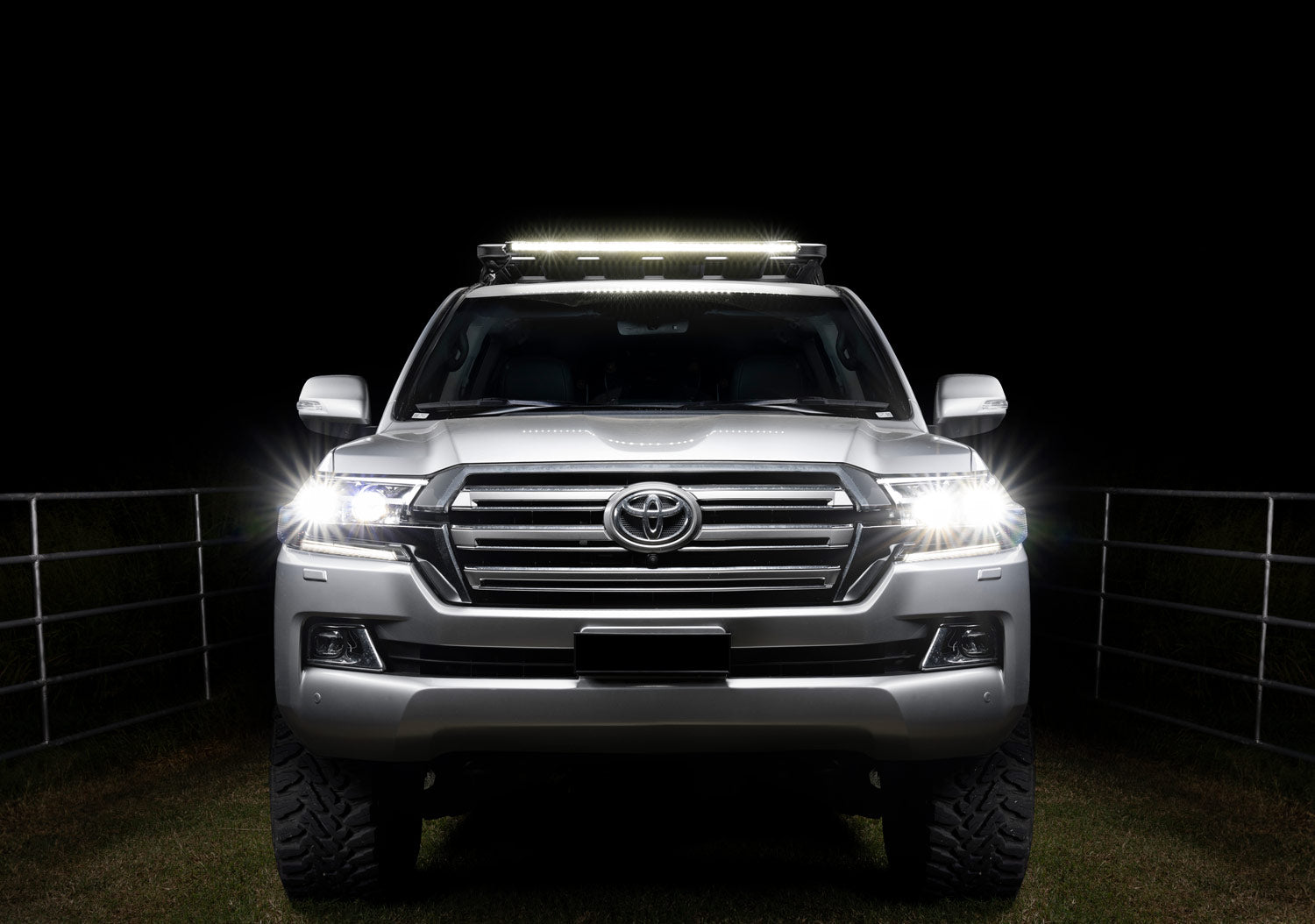
The Hyperion Driving Lights are designed for practicality. Unless you’re crossing the Nullarbor at night, the one-lux distance will see you through almost any stretch of road you take it down in comfort. The 110 degree short range beam angle will leave no surprises on the side of the road. Even the lens cover stays practical with the notched design, allowing the signature daytime running lights (DRL) shining while your light stays protected.
Index
PRODUCT OVERVIEW

The Hyperion Driving Lights have been put to all critical tests during development. Whether you fancy a territory trip in mid summer or want to explore the Snowys in July, your lights won’t fall apart, backed by our -40°C—85°C rapid temperature cycle tests. The IK09 (10 joule) impact rating means that this light can cop a stray branch to the face while trundling along an overgrown track without flinching. While not advised, if you need to bounce along the corrugations of the Strzelecki Track at dusk and need the extra visibility, the lights are tested to vibrations all the way down to 17Hz, at 20G accelerations. Even if you’re just plain clumsy, this light has been dropped on every face plenty of times to know that if you slip while installing it, the only thing hurt will be your pride.
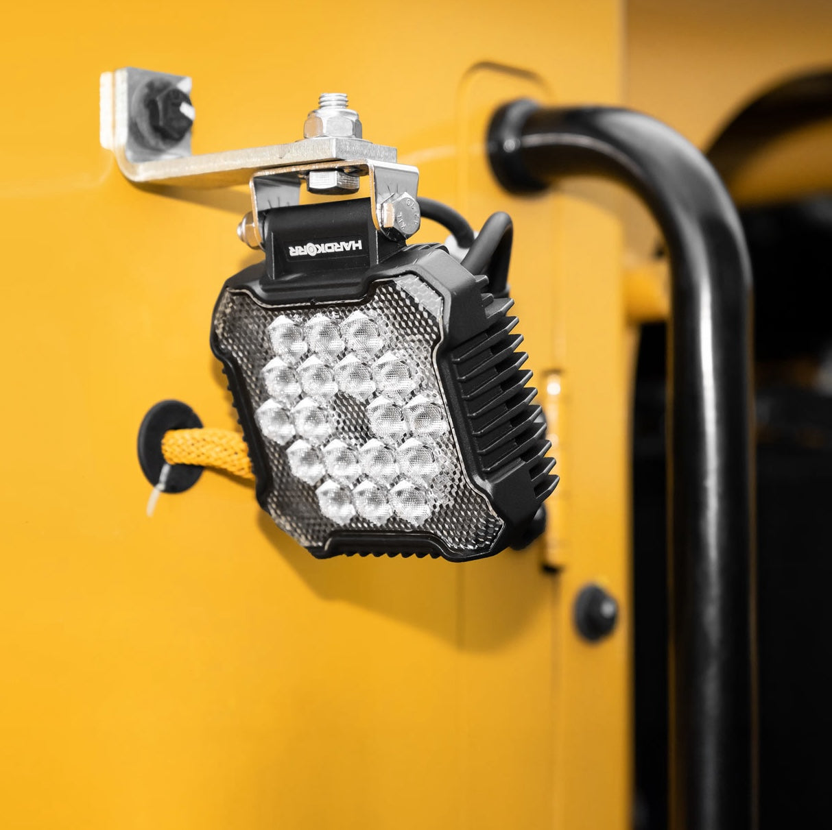
These lights have a 15 degree range of motion to get the beam just right, secured with the lower angle-adjustment bolts. We’ll get to the proper adjustment of the light beam in a little bit. Each light is fitted with a surface-mounted 3-pin socket to make dealing with the lights a breeze. Above the socket is the breather valve, designed to prevent moisture building up inside.
“But Hardkorr!”, you say, “Aren’t these lights IP68/9K rated?” While the Hyperion Driving Lights are rated for some of the most extreme conditions when it comes to water ingress, the air around us (including air within the light) contains some amount of moisture. While we’ve taken care to purge as much moisture from inside the light as possible, the breather valve allows the light to equalise pressure when the light heats up. This reduces condensation buildup and keeps your light good as new for a long time.
PACKAGE CONTENTS

Your Hyperion Driving Lights should come with everything you need to get your vehicle equipped. Other than the lights themselves, you’ll also find a pair of black HK lens covers and two titanium grey accent rings along with the tool that you can use to remove the existing rings. It also comes with a dual-output wiring harness and a couple of common headlight piggyback adaptors to get you started. Mounting hardware is included, with three stainless steel M10 bolts, washers, nuts and rubber mounting pads for each light. Your warranty card is also included.
INSTALLING THE HARNESS
This step can be daunting if you’ve never done it before. Rest assured, you’ll have little trouble following this guide. While there is some complexity to positioning of different components, it just comes down to how tidy you want the job to be. So long as the wires are away from any moving parts or areas that produce heat, you’ll be ok!
Firstly, you’ll just want to locate these five parts of your engine bay that are involved with this task. These include:
- The battery - where you will connect your lights to your vehicle’s power,
- The fuse-box - where you’ll intercept power for the DRL either in the engine bay or cabin,
- The headlamp plug - where you’ll intercept the high-beam circuit for your vehicle’s lights,
- A path through the grille - where you’ll direct the harness outputs to meet with your new lights, and
- A firewall grommet - where you’ll feed cables through to have a switch in the cabin.

Before you begin, make sure you have confirmed the headlight plug adaptor, and the fuse tap adaptor you will need. The last thing you’d want to happen is getting stuck into the installation and realise you need to head out for parts.
For your headlamp, you need to determine what kind of plug it has, so you can get the right adaptor, known as a ‘piggyback’ adaptor. The included piggyback adaptors work for many older vehicles, but newer vehicles often have their own unique plugs. We stock a wide range of piggyback adaptors. If you can‘t find a piggyback adaptor for your vehicle, you may need to consult with an auto-electrician for a more tailor-made solution.
For the fuse-tap adaptor, you need to take a look inside your fuse-box. Locate a fuse for a circuit that gets power at ignition, using a fuse-box diagram for your vehicle. Common circuits would be the air conditioning, power windows, the radio, or interior lights. These are often found inside the lid of the box. There are two fuse-tap adaptors included in the box, both for two different sizes of blade fuses. If neither of these are suitable, you can find the appropriate kind of adaptor at your local automotive retailer.
All of the terminals and plugs on this harness are unique, so you can’t really put something in the wrong spot.
Please ensure you have all the necessary parts before proceeding with this guide
1. Disconnect the negative terminal
Before you do any electrical work in the engine bay, it’s good practice to disconnect the negative terminal from the battery. Please note, if you have a vehicle that forgets radio codes or saved stations without a battery, you can pick up a handy product called a ‘memory minder’ from your local automotive retailer. It’s not essential, but quite helpful.
2. Mounting the relay
The black box at the end of the of cables is your relay. Find a secure spot in the engine bay somewhere close to your battery. The relay can be attached using an available bolt point (and fastening it with a nut), or with a self-tapping metal screw if necessary.
3. Attaching the positive cable
Now, attach the fork terminal of the red positive cable coming from the relay to the corresponding positive battery terminal. That’s one cable now sorted and out of the way.
4. Fitting the piggyback adaptor
Unplug the main headlamp bulb’s wiring. You will now have a loose plug unplugged from the light, and a loose socket on the back of the light. Your piggyback adaptor bridges this gap. Connect the ends of the piggyback adaptor to the corresponding ends of the headlamp and wiring.
All you’ll be left with is a small white 2-pin plug. Now, run the cable on the wiring harness fitted with a white 2-pin connector, so it meets the plug on the piggyback adaptor. You can run the cable around the back of the engine bay along the firewall, or along the front near the grille. Connect the plugs together.
5. Mounting the switch
Take a photo of the back of the switch to help you remember what colour wires go to which pins. Remove the switch from the harness by gently pushing on the small release tab on the spade terminals with a flathead screwdriver, and pulling on the terminals (not the wire) to unplug them. Put the switch on the driver’s seat so you don’t lose it.
Pass the switch wire through the cable grommet in your firewall, and gently pull it through from inside the vehicle.
Most vehicles have a small group of slots with dummy switches or blanking plates beside the steering wheel, or in the centre of the dash. Access the back of this panel to remove one of the blanking plates. Route the wire through the panel hole that’s left over.
Attach the wires to the correct pins on the back of the switch using your photo from earlier as a guide. If you lost track of where they go, consult the diagram at the end of this section. Push the connected switch into the panel hole until you hear a click, and your switch should now be secure. Close up any panels you removed and that’s it for inside the vehicle.
6. Attaching the DRL wire
If you’ve not done so already, locate a fuse within the fuse-box that has power on ignition. Remove the fuse in the slot you’ve chosen, and insert it into the bottom slot of the right sized fuse-tap. Insert the fuse-tap back into the empty slot you just made. Use one of the included blade fuses and insert it into the top of the fuse-tap.
Route the part of the harness with the yellow wires and spade-terminal ends towards the fuse-box somewhere safe and tidy. Connect the spade terminal to the installed fuse-tap. You may need to run the cable through a grommet in the side of your fuse-box if the lid doesn’t have a dedicated opening. If the fuse-box is located inside the cabin, follow the same procedure as in Step 5 regarding the firewall grommet.
7. Readying the light connection
Push the two connectors with orange rubber tips through the grille, using the path you found earlier. Keep the wires tidy and away from any moving parts like fan blades that may be nearby. You can now plug these connectors into the back of your lights when installed. The principle is the same if you are mounting your lights elsewhere on the vehicle.
8. Reconnect the negative terminal
Take the remaining black wire with the fork terminal, as well as the original negative cable you removed, and reconnect the wires to the negative battery terminal. If you used a memory minder, you can remove that too.
9. Tidying up
All that’s left to do is tidy up the wiring you’ve laid around the engine bay. You can use velcro straps, cable ties, or for a semi-permanent solution, wiring loom tape. If you use cable ties, don’t tighten them to much or you’ll risk potential damage to the wires. Follow existing paths of wires where possible, as they are already in an area deemed safe.
MOUNTING THE LIGHTS
Firstly, you’ll want to work out where you want to install the lights. This is usually as simple as utilising the mounting points on your bull bar or nudge bar, you may not have the luxury of predetermined placement. For bars with a wholly tubular construction, you can find clamp brackets at your local automotive retailer. Failing that, there’s always your trusty drill driver and a bit of determination. Make sure to seal any holes drilled with appropriate rust-proofing. Follow all state regulations on safe and correct driving light placement.
Start by fitting the M10 mounting bolts into the light bracket. You can do this by loosening the angle-adjustment bolts and tilting the light upward. This gives you plenty of room to slot the bolts in place without taking the entire bracket off. All three mounting holes should be used to secure the light as firmly as possible. Place the mounting pad over the mounting holes on your bar and lower the driving light into place, sliding the bolts into the holes as you go.
Once the light is seated and stable, fasten the bolts with the remaining hardware, threading on the flat washer first, then the spring washer, and finally the lock nut, tightened with a 17mm socket or spanner. For now, leave the outer two bolts slightly loose so you can adjust the angle of the light beam.
LIGHT COVER REMOVAL & ATTACHMENT
Before driving with the covers on, ensure you have removed any protective film from both the cover and the lens of the light. The driving light covers are held on with small tabs on the top and bottom that fit into slots in the body of the light. The cover can be removed with just one simple step. Simply apply pressure to the finger hole at the top of the cover until the tabs at the top are freed from the slots in the light body. You can now pull the cover away from the light.

To attach the cover, align the tabs on the bottom of the cover with the corresponding slots at the bottom of the light. Push the top of the cover into the light until you hear a click. This is the top tabs snapping into place.

ADJUSTING THE LIGHT BEAM
For this adjustment you’ll need a 4mm hex key, a 5mm hex key, and a spirit level. As the angle of the light beam is going to be relative to their position on the vehicle, you may also want to simulate how your vehicle will be loaded when you intend to use the lights for a more accurate result.
The angle of the light is secured with two central pivot bolts, and two locking bolts. Loosen all of the angle adjustment bolts with a 4mm and 5mm hex key until the light can be pitched manually with some light force. Take a spirit level and rest it vertically against one of the lights. Adjust the angle of the light until the the spirit level is plumb (vertical). Tighten the bolts again, and repeat the adjustment with the next light.
Park your vehicle on a flat, level surface. Start by loosening the mounting bolts just enough that the lights can rotate with some light force. Take your spirit level and press it up to the front face of both lights. Gently press against the front of both lights with the level while rotating the lights until both are flat against the level. This will align the light beams in parallel with each other. Tighten the mounting bolts again until the lights are secure.
This alignment method does not take into account some variables like variations in the vehicle mounting surface, so it’s best to test your driving light alignment at night, on a quiet country road, or empty shopping complex parking area. Remember to take your tools with you, and as best practice, keep a set of adjustment tools in the car for future modification. Before you turn on, ensure the vehicle is not pointed towards a house or person. With enough distance ahead of you, you’ll quickly be able to ascertain whether the lights need to be adjusted further.
ACCENT RING REMOVAL & ATTACHMENT
We’ve included an alternate pair of accent rings in the box. There is also an included lever tool to pry the rings from the light. With the tool in your hand, insert the prying tab on the tool into the slot on the bottom of the light. Rotate the tool to the left or right and the ring will pop off at the bottom. Pull the ring towards you from bottom to top to complete the removal process.

Attaching the accent ring is just as easy, however you’ll first want to make sure the ring is in the right orientation. On the back of the accent ring is a T-shaped tab. Position the T-shaped tab at the bottom of the ring, and align it with the slot on the bottom of the light housing. Push the rest of the ring onto the light from bottom to top to attach the ring.

WARNING: Do not operate the light with the black light covers attached. The black covers can absorb heat and become unsafe to handle with bare hands.
PRODUCT SPECS
| Specification | Hyperion 4" | Hyperion 7" | Hyperion 9" |
|---|---|---|---|
| Housing material | Powder-coated die-cast aluminium | ||
| Bracket material | Powder-coated die-cast aluminium | ||
| Lens material | UV-coated polycarbonate | ||
| Reflector material | Polycarbonate | ||
| Cover material | Polycarbonate | ||
| Accent ring material | Polycarbonate | ||
| LED type | 10 × 5W 2016 LEDs | 25x 5W 2016 LEDs | 35 × 5W 2016 LEDs |
| Operating voltage | 10–32V DC | ||
| Raw lumens (pair) | 7,890 lm | 17,674lm | 22,000 lm |
| 1 lux distance (pair) | 465 m | 935 m | 1,183 m |
| Beam angle | 110 | ||
| Colour temperature | 5500K | ||
| Ingress protection | IP68 / 9K | ||
| Current draw 12V (pair) | 7.2A | 12.7A | 23.8A |
| Current draw 24V (pair) | 3.6A | 6.35A | 11.9A |
| DRL power draw 12V (pair) | 0.6A | 0.7A | 1.2A |
| DRL power draw 24V (pair) | 0.3A | 0.35A | 0.6A |
| Operating temperature | -40°C – 85°C | ||
| Weight (each) | 0.64 kg | 1.66 kg | 2.8 kg |
| Certifications | CE, RoHS, R10/CISPR 25 | ||
| Warranty | 5 years | ||