


This guide contains all the information you need to know to get your new gear up and running, along with handy links to any available accessories and other relevant information. If you require technical support, please contact our support team for assistance. Contact details are contained within this guide.
-
Inverters should be installed by licensed professionals only.
-
The inverters are only suitable for 12V connections in mobile applications.
-
Before installing, cleaning, or inspecting the unit for maintenance, ensure that all
-
AC/DC loads and connections are disconnected. Ensure the inverter switch is in the off position before connection.
-
Children, inexperienced users, or persons under the influence of drugs/alcohol should not operate this unit.
-
Do not wear metallic items (jewellery) when working on/near live electrical equipment, as they are conductors and can cause electric shock or burns leading to serious injury or fatality.
-
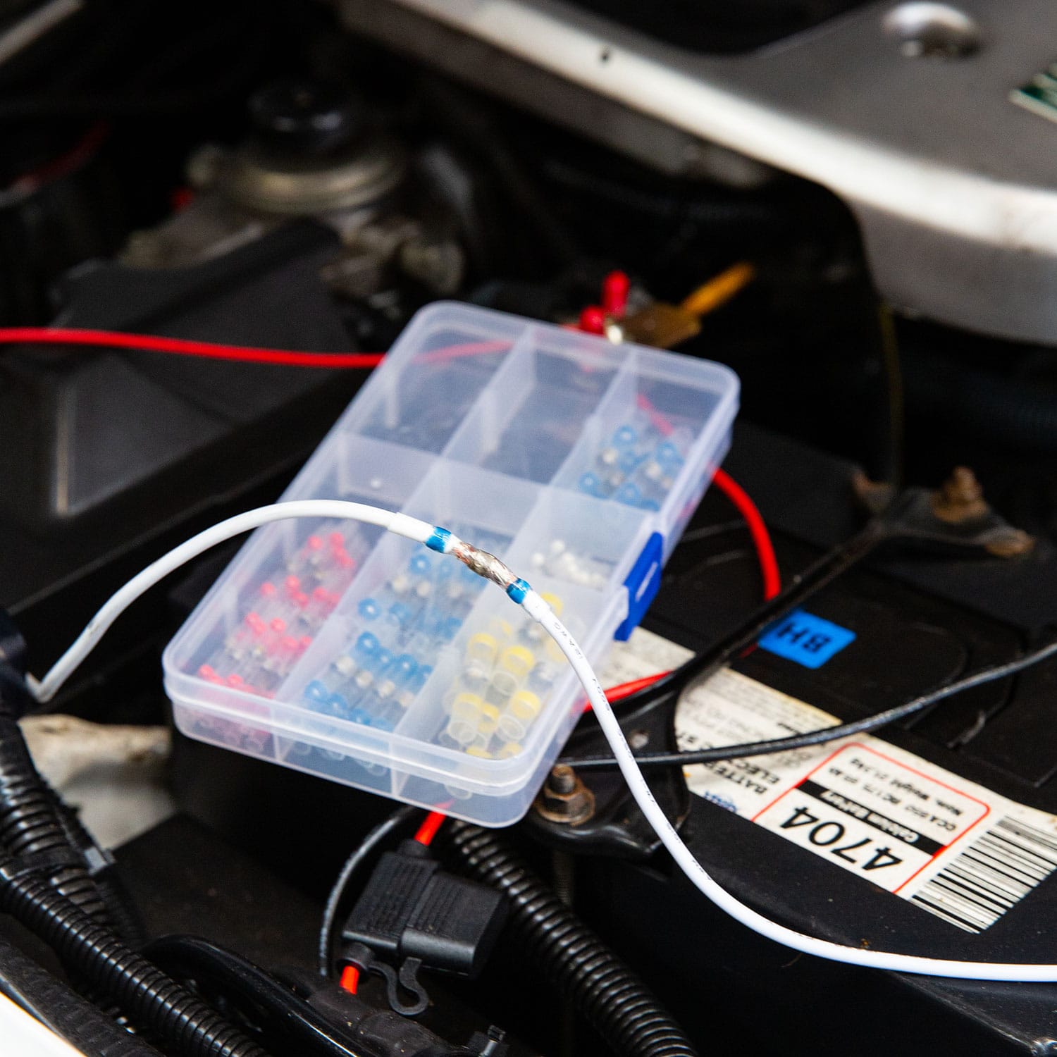
Before wiring up the inverter, make sure to inspect your leads to make sure they are free from faults or frays. The cables used to connect the battery to the inverter need to be of a particular gauge. Failure to use leads fit for purpose may cause fire, shock, or damage to the unit.
-
Do not over-torque or over-tighten the terminals. This could potentially damage the unit.
-
Ensure all 240V appliances in use have been annually tested and tagged unless new.
-
You must use the correct specified fuse when installing this product. See full guide for details.
-
Reverse polarity will cause irreversible damage to the inverter and is not covered by the manufacturer warranty. Ensure that the negative (-) and positive (+) terminals are connected to the correct corresponding battery terminals.
-
It’s common for the inverter to arc when wiring up the final connection. Make sure to keep any flammable materials away from the installation area.
-
Do not store or operate the inverter in a location where it may be subject to water, temperatures below -20°C or above 45°C, or in areas where it's at risk of contacting chemicals, fumes, or gases.
-
The inverter contains sensitive electrical equipment which may be damaged if the unit is subjected to pressure or impact. Ensure that the inverter is securely mounted to prevent it from falling. See full guide for correct mounting orientation.
-
Ensure that the unit fans and vents are clean and unobstructed. We recommend having at least 100mm of clearance around the unit to allow for adequate airflow.
-
The inverter should only be used with appliances that are in safe working condition.
-
Make sure to inspect both the wattage of the appliance and its leads and wires before operating.
-
Any 240V AC electrical works must be conducted by a licenced 240V electrician.
-
NEVER connect the AC output of the inverter directly to an electrical breaker panel/load centre which is also fed from shore power/generator.
-
The inverter should not be opened or disassembled under any circumstance. Doing so will void the warranty and may cause damage/injury to those in proximity.
PRODUCT OVERVIEW
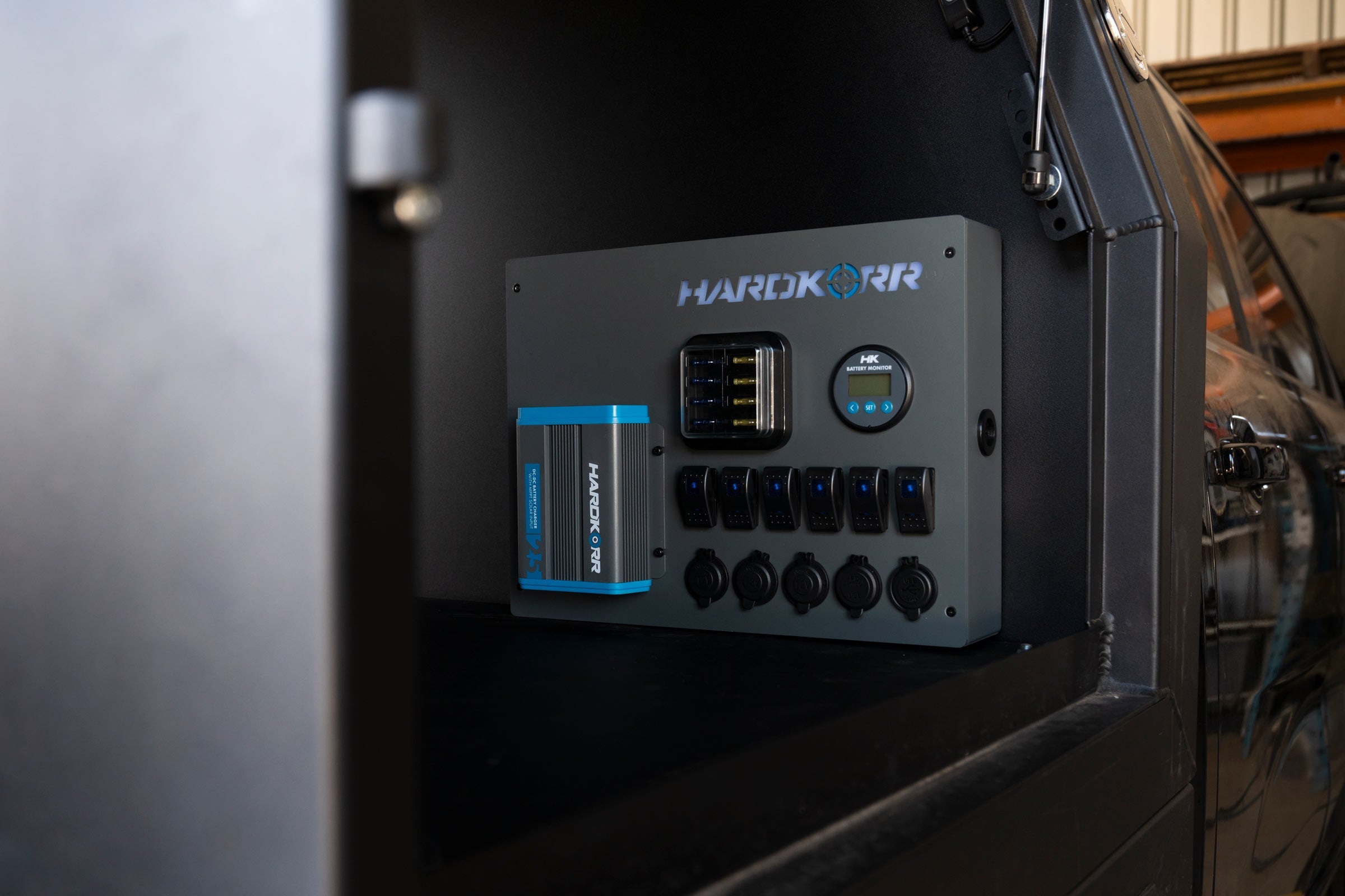
Our Pure Sine Wave Inverters are designed to convert your 12V power from your battery system, into safe and reliable 240V power. This allows you to operate appliances you’d usually run off AC/mains power from the comfort of your caravan, camper, or touring setup wherever you’ve decided to set up.
INSTALLATION
The inverter should be mounted in a position that fits the following criteria:
- STABLE - The inverter must be mounted on a surface capable of holding its weight, using all four mounting points with the appropriate fasteners.
-
ORIENTATION - The inverter can be mounted in any direction, including upside down if a canopy build permits it. Horizontally is the most secure mounting orientation, with the weight being distributed across both brackets evenly.
- CLEARANCE - Ensure the devices you intend to plug into the inverter have adequate clearance to the mounting surface. You may need to space the inverter out from the mounting surface for some large USB Adapters, laptop transformers or similar devices.
- DRY - The inverter must be mounted in an area free from water ingress of any kind.
- COOL - For optimal operating conditions, choose a location that stays within the temperature range of between 0°C and 40°C.
- SAFE - The inverter must be mounted in an area free from fumes and other hazardous substances.
- VENTILATED - Ensure a margin of at least 100mm around the inverter to reduce heat build-up.
- LIMITED DUST - The inverter must be mounted in an area with little to no dust ingress to reduce the likelihood of dust being drawn in by the fans when in operation.
- ELECTRICALLY SAFE - Ensure the inverter is mounted close to the battery to reduce any significant drop in voltage. With this in mind, the inverter must not be mounted within 300mm of the battery. A fuse must be fitted between the inverter and battery on the positive cable, with the fuse fitted close to the battery end to protect the cable.
Before installing your inverter, consult your battery’s user guide to make sure they are:
- Operating as a dedicated 12V battery.
- Of either an SLA, AGM, Gel, Calcium, or LiFePO4 chemistry.
- In good working order, free from any fault or damage.
- Additionally, the batteries should be equipped with a high enough continuous discharge rate to cater to the highest draw of the inverter. The guide below details the maximum current draw for each inverter.
The inverters are also able to be powered by systems running with batteries connected in parallel. For some batteries, the maximum continuous discharge rate will be increased when paralleled with a compatible unit. Before wiring the inverter to a parallel setup, consult your battery’s user manual to ensure that it matches the above criteria. Below is a guide outlining how the inverter should be wired to a parallel system.
CABLE & FUSE GUIDE
FUSES MUST BE FITTED CLOSEST TO BATTERY POSITIVE TERMINAL
The cable between the inverter and battery must be of a large enough gauge to prevent significant voltage drop over the length of the cable. Because voltage drop occurs between the battery positive and ground, the total cable length combined (positive and negative) needs to be considered.
NOTE: The cables should be routed in a way that prevents them from being damaged. Consider cable conduit or protective tubing to reduce abrasion.

CHASSIS GROUNDING
The inverter must be grounded properly before operating. Failure to do so will increase the risk of damage or injury.
The inverter's dedicated grounding point can be found on the long side of the unit, close to the AC outlets.
Ground the unit using a cable with an appropriate gauge by screwing the cable into the inverter’s grounding point. The other end of the cable should be attached to an appropriate earthing point – this may be the vehicle frame or the battery’s negative terminal if it has been grounded.

We recommend the following cable sizes for each inverter:
- 1000W model - 18AWG
- 2000W model - 16AWG
- 3000W model - 14AWG
SETUP DIAGRAM
The inverter can be correctly set up with a few simple rules.
- The fuse should be placed close to the battery end of the positive cable.
- If using busbars for attaching multiple accessories, a secondary fuse can be placed towards the inverter end of the positive cable.
- If using a battery monitor, the shunt should be placed close to the battery end of the negative cable.

CONNECTING THE BATTERY
- Before proceeding, ensure that you have the appropriate-sized cables and fuses outlined earlier in this manual.
- Remove the nuts and washers from the inverter’s terminals.
- The positive and negative cables should then be firmly fastened to their respective input terminals. Connect the positive lead first, by threading the cable eye and washers over the bolt, then fasten it with your nut so it’s secure. Repeat this process with the negative lead.
- Now, fasten the inverter terminal covers onto the inverter. They can be found in a bag inside the packaging.
- These cables should then be connected to the battery/DC power source. Fasten them first to the positive terminal, then the negative. Ensure that the positive lead has an appropriately sized fuse placed close to the battery.
OPERATING THE INVERTER
After wiring up the input side, the inverter is now ready to run your 240V appliances. Before operating the inverter, make sure that the appliance/s you intend on running have a total/cumulative wattage that is below the inverter’s rated wattage. Below outlines the process of running your appliances off the inverter.
- When running the inverter from 12V, make sure the battery has enough capacity to be able to run the inverter.
- Plug the appliance into the unit’s AC output socket.
- Turn the inverter on, either using the onboard switch or with the optional remote.
- Switch the appliance on.
- To turn the inverter off, first switch off and/or unplug the 240V appliance, then press and hold the power button on the inverter unit or optional remote.
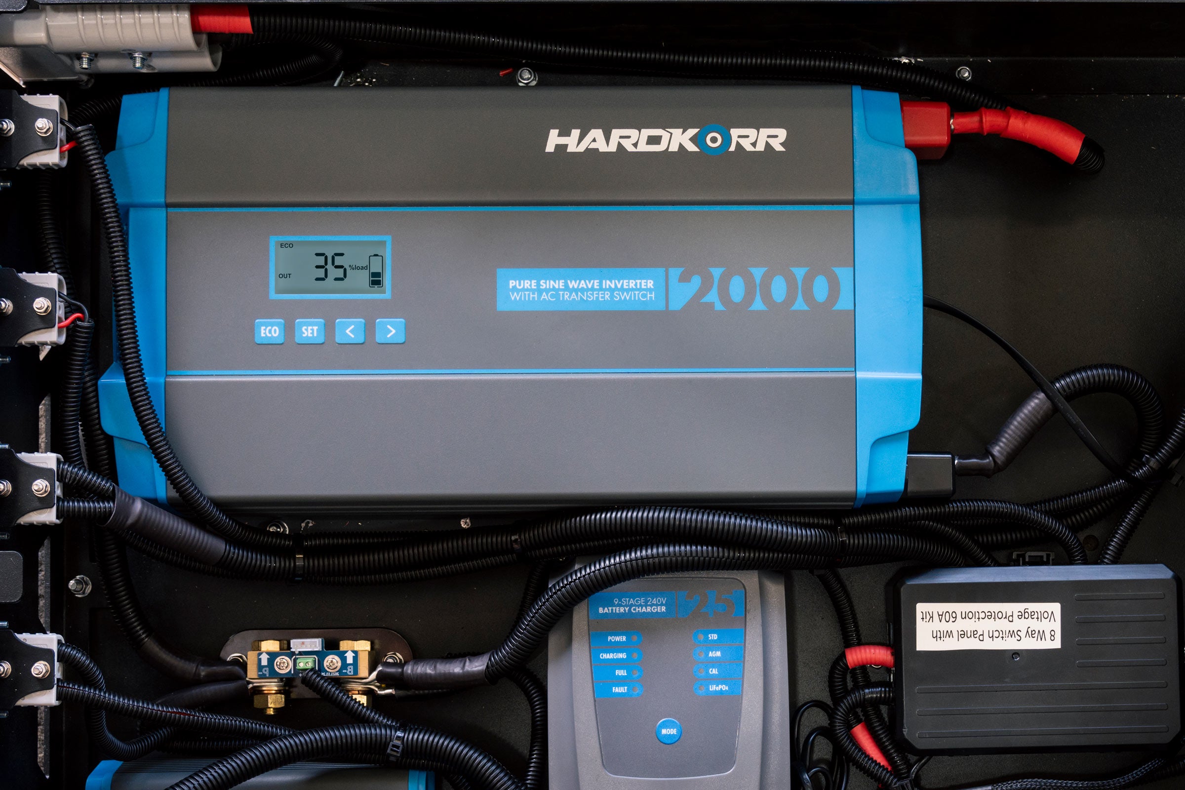
DIGITAL DISPLAY
The inverter unit has a bright digital display which has a readout of the load (in watts), an indicator to show the battery voltage state of charge, and an alternating readout of the AC voltage output, as well as the DC voltage input.

REMOTE ON/OFF SWITCH
The remote on/off switch will display identical information to the screen on the inverter itself.
The remote can be attached by simply plugging the included communications cable into both the inverter and the remote. The ample length of the cable allows you to position the remote a substantial distance away from the inverter while still being able to control it.
Turning the inverter ON and OFF via the remote:
Remote batch 112501:Hold the remote switch power button in for 0.5s --> inverter powers ONHold the remote switch power button in for 0.5s --> inverter powers OFF
Remote batch 032602 and later:Hold the remote switch power button in for 3s --> inverter powers ONQuick press the power button --> remote display turns OFF, but inverter stays powered ONQuick press the power button --> remote display turns back ON, inverter stays powered ONHold the remote switch power button in for 3s --> inverter powers OFF
TROUBLESHOOTING
| No power | The unit is off. Press the power button. If the fan starts but the display is off or your 240V appliance does not receive power, turn the inverter off immediately and contact Hardkorr. |
| No input voltage to the inverter | Check the DC connection for any faults or loose connections. |
| DC fuse blown | Make sure you have installed the correct fuse, or ask a qualified technician to check the system and replace the fuse. |
| LCD display not lighting up | Listen for the corresponding alert tones shown below. |
| Fault indicator alerts tones |
|
| Overload protection mode in effect | The unit needs to be turned off and back on again. |
| Short circuit protection mode in effect | The unit needs to be turned off and back on again. |
| Over temp. protection mode in effect |
Pre-circuit Over-temperature protection: 100±5℃ To recover the unit from the over-temperature protection, it will need to be turned off and back on again. |
| Low temp. protection mode in effect |
Pre-circuit Low-temperature protection: -30±5℃ To recover the unit from the low temperature protection, it will need to be turned off and back on again. |
| High fan speed on startup | The load connected is greater that 600W. |
| Low fan speed on startup | The load connected is between 200-600W. |
| Fan shuts off after startup | The load connected is less than 200W. If the fan is off and the draw is more than 200W, stop using the device and contact Hardkorr. |
SPECIFICATIONS
| Specification | HKPINV1000LS | HKPINV2000LS | HKPINV3000LS |
|---|---|---|---|
| Continuous power | 1000W | 2000W | 3000W |
| Input voltage | 12V DC | 12V DC | 12V DC |
| Output voltage | 240V AC ±5% | 240V AC ±5% | 240V AC ±5% |
| Peak surge (0.2 sec.) | 2000W | 4000W | 6000W |
| Max. efficiency | >93% (30% load) | >94% (30% load) | >93% (30% load) |
| Frequency | 50Hz ±5% | 50Hz ±5% | 50Hz ±5% |
| Total harmonic distortion (THD) | ≤5% | ≤5% | ≤5% |
| Under voltage protection range | 10.0V ±0.5V DC | 10.0V ±0.5V DC | 10.0V ±0.5V DC |
| Over voltage protection range | 15.5V ±0.5V DC | 15.5V ±0.5V DC | 15.5V ±0.5V DC |
| Overload power | 1100W ±100W | 2200W ±120W | 3200W ±120W |
| AC sockets | 2x Type I 10A | 2x Type I 10A | 2x Type I 15A |
| Power control | AC on/off switch (button) | AC on/off switch (button) | AC on/off switch (button) |
| Cooling fan | Thermally controlled | Thermally controlled | Thermally controlled |
| Dimensions (mm) | 260 (L) x 180 (W) x 87 (H) |
360 (L) x 190 (W) x 95 (H) |
412 (L) x 190 (W) x 95 (H) |
| Weight (approx.) | 1.6kg | 2.98kg | 4.1kg |
| Operating temp. | -20℃~45℃ | -20℃~45℃ | -20℃~45℃ |
| Storage humidity | 20%~85%RH | 20%~85%RH | 20%~85%RH |
| Certifications | CE, RoHS, AS/NZS 4763:2011AS/NZS 3112:2017 Inc A1:2021AS/NZS 3100:2022 Inc A1:2023 A2:2024 | ||
| Warranty | 2 years | ||